In this project, we will take a look at an interesting product called the WS2812B Addressable LEDs. They are individually addressable RGB LEDs and are also called by different names like NeoPixel by Adafruit, for example. In this tutorial, we will learn about the WS2812B LEDs, its internal structure and construction and also how to control individually addressable LEDs using Arduino.
Introduction
If you have made some sort of LED related project, then you probably might have used discrete LEDs (either through hole or SMD). These LEDs may be single color LEDs or RGB LEDs.
The main drawback of discrete LEDs is that if you use them in an array, you lose the privilege to control them individually. For example, if you connect three or four LEDs to a single pin of Arduino using a transistor, then all the LEDs in the array will have a same behavior i.e. brightness control or color change.
Another scenario is that you might have also used LED Strip Lights for Christmas decoration or regular home lighting. You might have observed that even in expensive LED Strip Lights, you do not have the feature to control individual LEDs.
If your aim is to control individual LEDs in a strip, then WS2812B Addressable RGB LEDs are the answer for you.
WS2812B Addressable LEDs
The WS2812B Addressable LED Strip is an intelligent light source that contains a control IC and an RGB LED in a same package, usually in SMD 5050 form factor. The following image shows a strip of WS2812B LEDs.
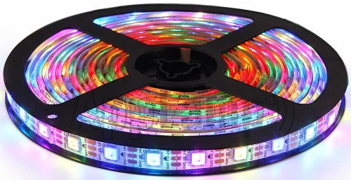
At first glance, it looks like a regular LED strip. But upon a closer inspection, you can find the WS2812B LED Control IC integrated into the SMD 5050 RGB LED Package. The following blown up image shows the same.
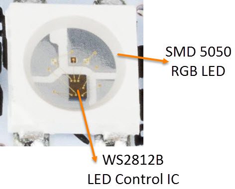
Individual WS2812B LED Block has four pins namely VDD, VSS (GND), DIN and DOUT. The functions of these pins are very simple and the following table gives a simple function description of the pins.
|
Pin |
Function |
|
VDD |
Power Supply for LED |
|
VSS |
Ground |
|
DIN |
Control Data Signal Input |
|
DOUT |
Control Data Signal Output |
The power supply for the WS2812B IC is also supplied through the VDD Pin.
WS2812B LED Application Circuit
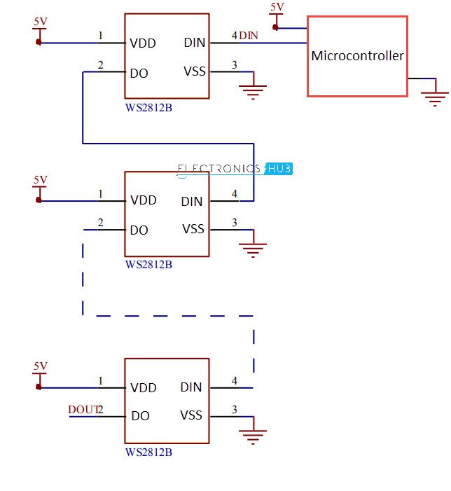
To understand how the WS2812B LEDs can be individually controlled, the following application circuit will be useful. All the WS2812B LEDs are connected in a cascade manner where the DO of the first LED is connected to the DIN of the second LED and so on.
But the first LED has to receive data through its DIN pin from a Microcontroller like Arduino. The following image shows the typical application circuit block diagram.
The data transfer protocol used by the WS2812B LEDs is NRZ Mode. The first DIN Port of the WS2812B LED array receives data from the microcontroller. The data for individual pixel is of 24-bit that consists of individual Red, Green and Blue LED control data of 8-bits each. The order of data must be GRB and the composition of the 24-bit data is shown below. Note that HIGH bit data is sent first.
![]()
Once the first WS2812B Block receives the first 24-bit data, the data is sent to its internal latch for further decoding. The remaining data is reshaped by its signal reshaping and amplification circuit and is passed to the next pixel in the cascade through the DO pin.
How to Control WS2812B LED using Arduino?
Now, let us proceed to control the WS2812B LED Array using Arduino. Before going further into designing the schematic, there is one important thing we need to address i.e. the power supply to the project.
Each Individual WS2812B LED Pixel has three LEDs and a control IC. So, the current requirement of one pixel is around 60 mA. If you have a strip that contains 20 WS2812B Individually Addressable LEDs, then the total current requirement is 20 * 60 mA = 1.2 A.
This is more than Arduino can supply, either through the USB port (which can supply a maximum of 300 mA) or through 5V barrel jack (which can supply a maximum of 900 mA).
So, the best way to power up the project i.e. both Arduino and the WS2812B LED Strip is with the help of an external 5v supply that can provide enough current.
Now that the power supply part of the project is clear, we can now proceed with the schematic of the project.
Circuit Diagram
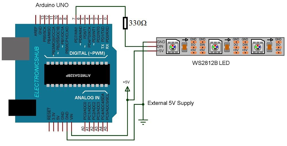
The following image shows connection between Arduino UNO and the WS2812B RGB LED Strip. The 5V of Arduino UNO and the LEDs are connected to an external power supply along with the GND (VSS).
The DIN pin of the LED Strip is connected to Digital IO pin 7 of the Arduino through a 330Ω Resistor.
Components Required
- Arduino UNO
- WS2812B LEDs
- 5V Power Supply (minimum 2A)
- 330Ω Resistor
Programming Arduino
The first step for programming Arduino is to download a supporting library called “FastLED”. You can download the library from the following link: “FastLED Library”.
Extract the contents of the zip file and rename the folder as “FastLED”. Move this folder to the libraries folder of the Arduino.
Code
#include <FastLED.h>

#define LEDPIN     7
#define NUMOFLEDS    10

CRGB leds[NUMOFLEDS];

void setup() {

  FastLED.addLeds<WS2812, LEDPIN, GRB>(leds, NUMOFLEDS);

}

void loop() {

  for (int i = 0; i <= 9; i++) {
    leds[i] = CRGB ( 0, 0, 255);
    FastLED.show();
    delay(40);
  }
  for (int i = 9; i >= 0; i--) {
    leds[i] = CRGB ( 255, 0, 0);
    FastLED.show();
    delay(40);
  }
}
Conclusion
A simple introduction to WS2812B Individually Addressable LEDs is given in this tutorial along a project to show how we can control WS2812B LEDs with Arduino. If you understand these basics, then you can implement a wide range of projects.

2 Responses
how can I make just the 1st led blink for a length of time using a button. then stop
i have 6 buttons , I want each button to do an action, then stop , and wait till another button is pressed. but each button has a set program to it.
I dont know if it is possible .
Thank You
I have the exact same question, can multiple buttons or switches activate different presets?