In this project, we will learn about Infrared Sensors, simply known as IR Sensor and how to interface an IR Sensor with Raspberry Pi. By interfacing this IR Sensor with Raspberry Pi, you can implement a Proximity Sensor Application (Obstacle Detection).
Overview
Infrared Sensors or IR Sensors are one of the frequently used sensor modules by electronics hobbyists and makers. They are often used as Obstacle Detecting Sensors or Proximity Sensors.
IR Sensors are also used in Contactless Digital Tachometers. Some of the other applications where IR Sensors are implemented are Line Follower Robots, Obstacle Avoiding Robots, Edge Avoiding Robots and many more.
Brief Note on IR Sensor (IR Proximity Sensor)
IR Sensors emit and receive Infrared radiation. They are often used as Proximity Sensors i.e. detect and alarm if an object is close to the sensor.
Let me help you understand better about IR Sensors by giving two real life applications of IR Sensors. The first one is Mobile Phones.
Almost all mobile phones nowadays have IR Sensors in them. Usually, they will be placed near the earpiece on the phone.
When the user make or receives a phone call, the IR Sensor detects how far the phone is from the user’s ear. If it is close to the ear, the phone’s display will be turned off so that you do not touch anything on the screen accidently.
Another important application is in automobiles. All modern cars are equipped with reverse parking sensor that sense how far you can reverse your car without hitting anything. These reverse sensors are implemented using IR Sensors.
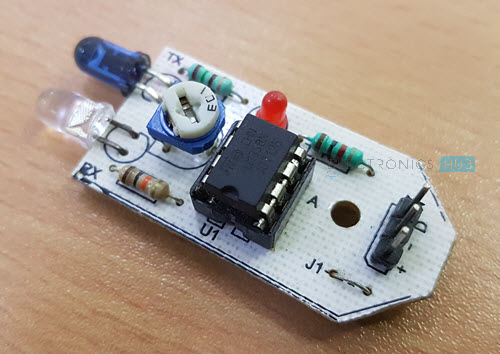
An IR Sensor Module basically consists of three parts: an IR Transmitter, an IR Detector and a control circuit.
Usually, an IR LED is used as an IR Transmitter and a Photo Diode or a Photo Transistor (less often) is used as an IR Detector. The control circuit consists of a Comparator IC with necessary components.
Based on the application and requirement, IR Sensors can be implemented in two ways. In the first method, both the IR Transmitter and the IR Detector are placed side-by-side. In the second setup, the IR Transmitter and the IR Detector are placed facing each other.
The first way of implementation is known as Reflective Type IR Sensor. In this setup, the IR Transmitter continuously emits infrared light and if there is any obstacle/object in front of the sensor, the infrared light hits the object and bounces back. The reflected signal is captured by the IR Detector and the control circuit will reflect a Logic HIGH on its output.
The second way of implementation, where the IR Transmitter and Detector are positioned face-t-face, is known as Transmissive Type IR Sensor. Here, the infrared light from the IR Transmitter always falls on the Detector.
If there is an object in between the Transmitter and Detector, then there will be an obstruction to the infrared light and the control circuit will detect this and produces appropriate output.
The IR Sensor used in this project is a Reflective Type IR Sensor. You can easily build this type of IR Sensor as a DIY Project as the circuit is very simple.
Schematic of IR Sensor Module
The following image shows the circuit diagram of the IR Sensor Module. It consists of the following components.
- IR LED
- Photo Diode
- 150Ω Resistor
- 10 KΩ Resistor
- 10 KΩ Potentiometer
- LM358
- LED
- 1 KΩ Resistor

Raspberry Pi IR Sensor Interface
Now that we have seen a little bit about the IR Sensor Module and its connections, we will proceed with interfacing IR Sensor with Raspberry Pi.
The Raspberry Pi IR Sensor Interface can be converted into a Proximity Detector, where the application will detect if the object is too close to the sensor.
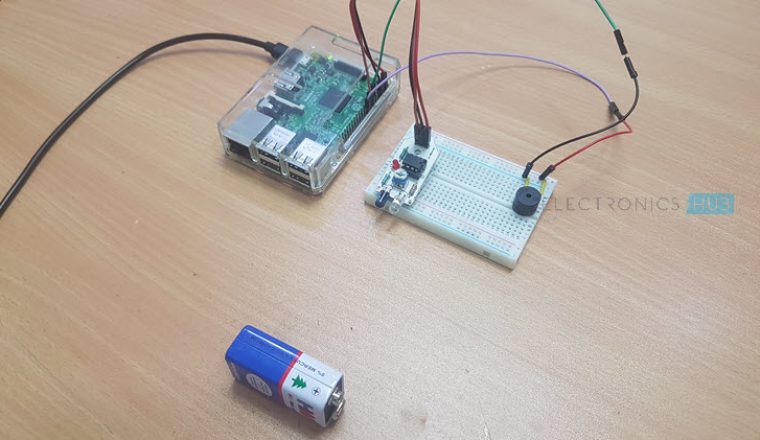
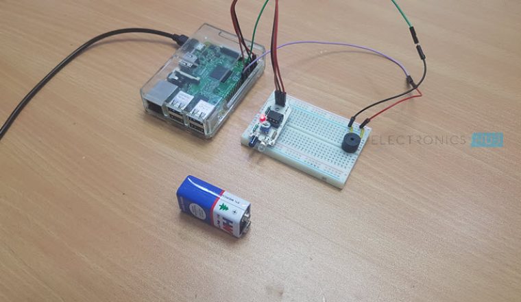
Circuit Diagram
The following image shows the connection diagram of Interfacing IR Sensor with Raspberry Pi. You have already seen the circuit diagram of the IR Sensor Module.

Components Required
- Raspberry Pi 3 Model B
- IR Sensor
- 5V Buzzer
- Mini Breadboard
- Connecting Wires
- Power Supply
- Computer
Circuit Design
The IR Sensor Module has only three Pins: VCC, GND and Data. Connect the VCC and GND pins of the IR Sensor to +5V and GND pins of the Raspberry Pi.
Then connect the Data pin of the IR Sensor to GPIO23 i.e. Physical Pin 16 of the Raspberry Pi.
In order to indicate the alarm, I have used a simple 5V Buzzer. Connect one terminal of the buzzer to GND of Raspberry Pi and the other terminal (usually marked +) to GPIO24 i.e. Physical Pin 18 of Raspberry Pi.
Code
The following is the code for interfacing IR Sensor with Raspberry Pi. It is written in Python.
Working
We have learned how to interface an IR Sensor with Raspberry Pi. I’ll now explain the working of the project.
All the magic happens in the IR Sensor Module. As it is a Reflective type IR Sensor, whenever an object is placed in front of the sensor, the Infrared light from the IR LED gets reflected back after hitting the object and falls on the Photo Diode.
The photo diode then starts conducting. As a result, the voltage at the non-inverting input of the LM358 will be greater than that at the inverting input.
Since the LM358 is acting as a Comparator, its output will become HIGH and the on-board LED glows. The HIGH on the Data Pin is detected by the Raspberry Pi and it activates the buzzer.
Using the 10 KΩ Potentiometer, you can adjust how far the object can be placed in front of the sensor in order to detect.
Applications
As mentioned in the earlier sections, Proximity Sensor or Obstacle Detection is the main application of interfacing IR Sensor with Raspberry Pi. Some of the common applications include:
- Contactless Tachometer
- Line Follower Robot
- Obstacle Avoiding Robot
- Car Reverse Sensor
- Mobile Proximity Sensor

5 Responses
thanks worked perfectly
Thanks a lot
Thank you very much.
Well done to teach this program.
nice
Thankyou it’s helped lot